Key Takeaways
- Cost-effective modernization: Vieworks panel retrofits deliver 30-50% cost savings versus full-room replacement while achieving 60-70% DQE (versus legacy CR at ~30%), extending equipment lifecycle 5-10 years without generator replacement.
- Quantifiable workflow improvements: Properly integrated DR systems produce 96% productivity increases, and 71% patient wait time reductions (43.5 hours to 4.62 hours), with image-to-PACS delivery under 90 seconds when configured correctly.
- Significant dose reduction: Modern DR panels reduce patient radiation exposure 56-67% while maintaining diagnostic quality, meeting ALARA requirements, and improving safety outcomes for both patients and staff.
- Integration complexity demands planning: With 84% of healthcare IT integrations failing due to poor planning, success requires systematic validation of five critical layers: detector hardware, generator synchronization, network connectivity, DICOM routing, and workflow optimization.
- Pre-installation verification prevents failure: Comprehensive scoping, room surveys, generator interface testing, network prerequisites, and stakeholder sign-offs eliminate surprises during implementation and ensure clinical acceptance before first patient exposure.
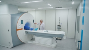
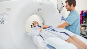
Upgrading to digital radiography doesn’t require replacing your entire X-ray room. Vieworks DR panels retrofit into existing infrastructure, delivering modern image quality and workflow efficiency at a fraction of full-room replacement cost, but only when integration is executed correctly.
This guide provides technical leaders, radiology administrators, and biomedical engineers with a systematic framework for Vieworks panel integration, from pre-purchase verification through long-term operational excellence.
What Is “Vieworks Panel Integration” And Why Does It Matter?
Definition: Vieworks panel integration refers to the compatibility between Vieworks digital radiography detectors and existing X-ray infrastructure, encompassing workflow optimization and technical interoperability. True integration coordinates multiple touchpoints: detector hardware, acquisition software, generator synchronization, network connectivity, and DICOM routing to PACS/RIS.
Why integration quality matters: Properly executed DR panel compatibility delivers a 96% increase in overall productivity and reduces patient wait times by 71% (from 43.5 hours to 4.62 hours), modern panels cut radiation dose 56-67% while maintaining diagnostic quality. However, 84% of poorly planned healthcare IT integrations fail, making careful planning critical. “Seamless” has measurable definitions: time-to-PACS under 90 seconds, repeat rates below 5%, routing success above 99%, and technologist interface clicks reduced 30-50% through protocol automation.
Why Choose Vieworks Panel Retrofit Instead Of Full Room Replacement?
Primary drivers: Vieworks retrofits cost 30-50% less than full-room replacement, require 1-2 days downtime versus weeks, and extend equipment lifecycle 5-10 years. Image quality leaps from legacy CR’s ~30% DQE to modern panels’ 60-70% DQE (latest dual-layer technology reaches 75%). Digital radiography workflow velocity improves through 45% faster image processing and 40% efficiency gains.
Vieworks retrofit advantages: Standard cassette sizes (14×17″, 17×17″) ensure broad compatibility across manufacturers. Wireless and wired options accommodate different room configurations. DICOM compliance guarantees seamless PACS integration without custom interfaces. Broad X-ray system integration eliminates vendor lock-in, allowing facilities to modernize detectors while preserving generator investments, extending the value of existing imaging equipment.
Pre-Integration Verification: What Must You Check Before Committing?
Critical room survey checklist: Verify Bucky tray dimensions and grid compatibility for your panel size (14×17″ or 17×17″). Confirm generator interface capability, whether analog exposure detection (AED) or digital prep signal. For wireless panels, validate Wi-Fi coverage meets -65 dBm minimum throughout the imaging area. Document network prerequisites: VLAN configuration, DICOM port 104 accessibility, and IP addressing scheme. Confirm PACS AE titles and routing rules are configured. Verify worklist source availability (RIS/MWL).
Key IT prerequisites:
| Item | Why It Matters | How to Validate |
| VLAN Segmentation | Isolates medical device traffic | Confirm medical device VLAN exists |
| Wi-Fi Coverage | Adequate signal for wireless panels | Site survey (-65 dBm minimum) |
| PACS AE Titles | Correct routing destinations | Test DICOM echo, verify in PACS |
| Worklist Sources | Automate demographics, reduce errors | Retrieve test worklist, verify data |
Clinical workflow decisions to lock: Establish exam protocol ownership and change control procedures before go-live. Define naming conventions and laterality rules to prevent routing errors. Document QC steps and repeat criteria. Create downtime/fallback procedures for when network or system issues arise, supported by comprehensive maintenance programs. These decisions prevent post-implementation confusion and ensure consistent, efficient operation.
Core Technical Integration: What Components Must Work Together?
Successful DR integration requires synchronized operation across five critical components. Each dependency point represents a potential failure mode; understanding these interactions prevents implementation delays and operational issues.
Essential component dependencies:
| Component | Integration Dependency | Common Failure |
| Detector/Panel | Physical mounting, exposure trigger, wireless pairing | Missed captures, battery drain |
| Generator Sync | AED or prep signal interface | Timing errors, short exposure failures |
| Network/Wi-Fi | IP addressing, bandwidth, roaming | Connectivity drops, slow transfers |
| PACS Routing | DICOM worklist (MWL), AE titles, routing rules | Wrong patient, orphaned images |
Generator synchronization decision: AED (Automatic Exposure Device) suits generators lacking digital interfaces, common in retrofit scenarios. Validate with short exposure tests: 40 kV, 0.5 mAs to confirm capture timing. The generator interface (prep signal) works with most post-2010 systems offering digital output. Requires full technique range validation from pediatric (low kV/mAs) to bariatric (high kV/mAs) to ensure reliable triggering across all clinical scenarios.
Implementation Approach: Key Steps For Successful Integration
Integration success depends on systematic planning, not just technical competence. Rushing deployment creates workflow friction that persists for years; methodical execution prevents post-go-live chaos.
Step 1: Baseline current workflow. Document current-state metrics: time per exam, patient wait time, and repeat rates. Review six months of failure history, including equipment downtime and rejection reasons. Map existing routing paths from modality through PACS to reporting. These baselines prove ROI and identify improvement targets.
Step 2: Choose architecture strategy:
| Architecture | Best Fit | Key Requirement | Risk Mitigation |
| Single-Room Dedicated | High-volume rooms (>40 exams/day) | One panel per room | Keep spare panel charged |
| Shared Detectors | Multi-room, lower volumes (<30/day each) | Panel tracking system | RFID tracking, status board |
| Multi-Room Wireless Pool | 3+ rooms, variable volumes | Charging stations, Wi-Fi roaming | Site survey, battery monitoring |
Step 3: Configure detector connectivity. For wireless panels, verify signal strength throughout the imaging area, test roaming between access points, check for interference sources, and establish battery rotation workflow. For wired panels, install strain relief at connection points, test cable flex cycles to confirm durability, and configure backup connectivity path.
Step 4: Optimize acquisition software to reduce clicks. Limit exam menus to active protocols only, remove legacy or rarely-used options. Pre-load technique parameters, image processing algorithms, and routing destinations per exam type. Enable auto-processing and auto-routing to eliminate manual steps. Configure user roles and permissions to prevent unauthorized protocol changes.
Step 5: Validate generator synchronization. Test the full technique range from pediatric (low dose) to bariatric (high dose) exposures. Validate edge cases: short exposures under 10 milliseconds and rapid repeat exposures. Document pass/fail criteria for acceptance testing, clear thresholds prevent subjective disputes during commissioning.
Step 6: Configure PACS routing. Assign unique AE titles per room or detector to enable granular troubleshooting. Set routing rules by exam type, chest studies to chest PACS node, MSK to orthopedic node. Configure retry behavior: three attempts with 30-second delays between retries. Test downtime buffer, panels must store images locally when PACS is unreachable, then auto-send on reconnection.
Validation And Go-Live: Ensuring Image Quality And Performance
Go-live without validation testing invites clinical complaints and erosion of staff confidence. Systematic acceptance testing proves seamless imaging systems meet specifications before patient care depends on them.
Image quality acceptance tests: Run uniformity phantom test confirming >95% uniformity across detector area. Establish SNR baseline at standard chest technique for ongoing quality monitoring. Perform an artifact detection scan confirming fewer than five defective pixels per one million pixel array. Verify grid alignment; no gridline artifacts should appear in clinical images.
DQE performance validation: Modern Vieworks panels achieve 60-70% DQE versus legacy CR/PSP systems at ~30% DQE, a 100%+ improvement in quantum efficiency. Latest dual-layer FPDs reach 75% DQE. MTF target should meet or exceed 66.5% at 1 line pair per millimeter. These metrics directly correlate to clinical image quality and dose efficiency.
Radiation dose validation (critical safety metric): Target 56-67% reduction in patient dose measured by kerma-area product (KAP). Specific reductions include 64% lower dose for hip imaging and 43% lower dose for shoulder imaging compared to CR. Staff benefit from 33% reduction in occupational dose exposure, which is important for interventional rooms with high procedure volumes and contrast media administration.
Post go-live monitoring metrics:
| Metric | Target | Review Cadence |
| Exposure Index Stability | ±20% of baseline | Daily (first month), then weekly |
| Repeat Rate | <5% overall | Weekly |
| Routing Success | >99% first-pass | Real-time alerts, daily dashboard |
| Time-to-First-Image | <90 seconds | Weekly average |
Essential clinical test cases: Routine chest PA/lateral with demographics auto-populated from worklist, achieving under 60 seconds to PACS. Extremity imaging confirming laterality tags and bone processing algorithms applied correctly. Portable workflow maintaining wireless connectivity during transport between rooms. A wrong-patient prevention scenario where the system flags similar patient names before exposure. Network drop scenario proving images queue locally and auto-send when connection restores, preventing lost studies during network instability.
Common Failure Modes And Prevention Strategies
Healthcare IT integrations fail 84% of the time due to poor planning. DR retrofits avoid this fate through specific prevention strategies targeting the three most common failure categories.
Wrong-patient/demographics issues: Root cause includes manual entry errors, stale worklists, and bypassed verification steps. Prevention requires enforcing MWL (Modality Worklist) use with no manual override option, implementing two-identifier hard stops before exposure, deploying barcode scanning for patient wristbands, and establishing reconciliation workflows that flag mismatches before images reach PACS.
Routing failures: Root causes include AE title mismatches after configuration changes, unannounced firewall rule modifications, and PACS downtime without fallback. Prevention strategies include AE title standardization across all devices, automated port monitoring with alerts for connectivity changes, queue/retry settings that store images locally during outages, and change management notifications requiring a 48-hour advance notice for network modifications affecting medical devices.
Image quality issues: Root causes include grid mismatch between detector and bucky, positioning drift over time, and unauthorized processing preset changes. Prevention requires grid compatibility verification during installation (line frequency, ratio, focal distance), technologist re-training at six-month intervals, version-controlled processing presets with admin-only modification rights, and monthly phantom QC with quarterly DQE validation by qualified medical physicists.
Troubleshooting: Quick Diagnostic Approach
Rapid problem isolation prevents extended downtime. Systematic triage identifies the failure layer within minutes, directing escalation to the correct support team immediately.
Rapid triage table:
| Symptom | Likely Layer | Quickest Test | Evidence to Collect |
| No image acquired | Detector/Sync | Check exposure handshake indicator | Detector status, exposure log, technique values |
| Image not on workstation | Network | Ping detector IP, check Wi-Fi | IP address, signal strength (RSSI), packet loss |
| Image not in PACS | DICOM/Routing | DICOM echo test, check send queue | DICOM send log, AE title, port status |
| Wrong demographics | Worklist/RIS | Query MWL manually | MWL result, RIS order, patient ID |
Critical evidence before escalation: Capture error messages with screenshots, including error codes. Document timestamps and frequency, single occurrence versus recurring pattern. Record network status: IP address, signal strength, VLAN assignment. Export DICOM send logs showing transmission attempts and responses. Note recent configuration changes within 72 hours, software updates, network modifications, or protocol adjustments. This evidence package enables vendor support to diagnose remotely, avoiding unnecessary site visits.
Long-Term Operational Excellence
Initial go-live success means nothing without sustained performance. Long-term excellence requires governance structures, redundancy planning, and continuous improvement mechanisms.
Standardization controls: Establish protocol governance through quarterly review committee meetings, in which radiologists, technologists, and physicists evaluate protocol performance and approve modifications. Implement change control requiring documented justification and testing before any protocol, processing, or routing modifications go live. Conduct annual technologist competency checks, verifying adherence to positioning standards and equipment operation. Perform monthly phantom QC with quarterly DQE validation to detect detector degradation before clinical impact.
Downtime/fallback procedures: Configure detectors to store images locally with automatic transmission when connectivity is restored, preventing lost studies during network instability. Deploy a backup DICOM storage appliance for PACS outages lasting over two hours. Maintain a spare detector in a charged and configured state, swap within 15 minutes for detector failures. Execute post-downtime reconciliation within 24 hours, verifying all queued images were transmitted successfully and no studies are orphaned.
Security and safety considerations: Assign separate user accounts by role: acquire (technologists), QC (lead techs), admin (physicists and IT). Deploy quarterly security patches and annual firmware updates during scheduled maintenance windows. Maintain network segmentation through a dedicated medical device VLAN, isolating imaging traffic from the general hospital network. Require technique chart validation by a qualified medical physicist annually or after any generator modifications. Monitor exposure index values, flagging outliers (±30% from baseline) for immediate investigation, to prevent chronic over- or underexposure.
AI integration opportunity: Vieworks VXCAD-CXR (licensed 2024) provides AI-powered diagnostic aid for chest X-rays, integrating directly with Vieworks panels. AI-enhanced systems achieve 83% accuracy and 81% sensitivity for suspicious lesion detection. Financial case studies document 791% five-year ROI for AI platforms integrated with rapid DR workflows, driven by earlier diagnosis, reduced callbacks, and radiologist efficiency gains.
Frequently Asked Questions
Can Vieworks panels work with our existing generator?
Most generators manufactured after 2010 have digital interfaces compatible with Vieworks panels. Vieworks supports both direct generator interface (prep signal) and AED (Automatic Exposure Device) methods for older systems. Validation test: perform 40 kV, 0.5 mAs exposure to confirm reliable capture timing across the technique range.
Do panels fit our existing Buckys?
Yes, Vieworks manufactures standard 14×17″ and 17×17″ cassette sizes that fit most buckys without mechanical modification. Grid compatibility requires verification, confirming that the grid line frequency, ratio, and focal distance match between the existing grid and the new detector specifications.
Can we share one detector across multiple rooms?
Yes, shared detector models work well for facilities performing under 30 exams per day per room. Requirements include a panel tracking system (RFID or manual log), Wi-Fi coverage meeting -65 dBm minimum throughout all rooms and transport corridors, and dedicated charging stations in a central location. Plan for a minimum of two panels in three-room setups, which prevents workflow bottlenecks when one panel charges.
What’s the typical validation timeline?
Budget 2-3 days for comprehensive validation testing. Day 1: connectivity verification, generator synchronization across the technique range, and network routing tests. Day 2: image quality acceptance (uniformity, SNR, artifacts, DQE), DICOM worklist integration, and clinical workflow scenarios. Day 3: staff training, documentation review, and final sign-off. Expedited single-day validation is possible for simple single-room retrofits with experienced integration teams.
Next Steps For Low-Risk Go-Live
Successful DR integration depends on thorough scoping before any purchase, since missed prerequisites discovered during installation can cause delays and workflow compromises. Collect the essentials up front, room photos, and Bucky measurements to confirm panel fit, generator make/model, and interface type, and network details (VLAN, Wi-Fi coverage, and available IP ranges), and identify PACS/RIS decision-makers. Export current protocols and repeat-rate data to set baselines, then define clear success metrics and timeline constraints to prevent scope creep.
Before the first patient, assign sign-off ownership across clinical leadership (image quality/ALARA), radiology operations (workflow/training), biomed (hardware and generator sync), IT (network/DICOM/cybersecurity), and the vendor (acceptance testing and support). With this governance and validation, Vieworks retrofits can deliver major gains in productivity and patient flow while reducing dose, without the cost of full-room replacement.
Ready to modernize your radiography department without full-room replacement costs? Contact Spectrum X-Ray’s integration specialists to scope your Vieworks retrofit project with confidence.